How to: Suzuki GS650 Wiring “From Scratch”
This fellow found me on thegsresources.com, then he found me on Facebook and sent a message.
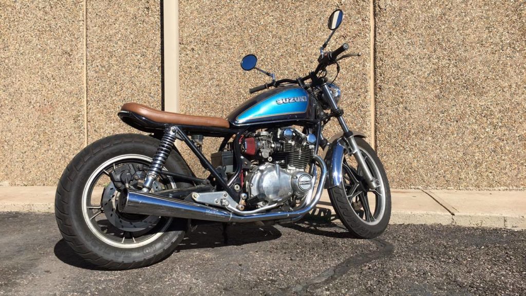
Last summer I brought an old GS650GL “back from the dead,” and here’s how it turned out:
Part of putting that bike back on the road involved building a wiring harness out of a bunch of wires and connectors.
I threw the old one in the trash because it was old and mangy. That said, it’s a good idea to keep your old wiring harness on hand for reference purposes. Because the bike is old and carbureted, it wasn’t that difficult to make a new one to run the “bare essentials.” Here’s how I did it.
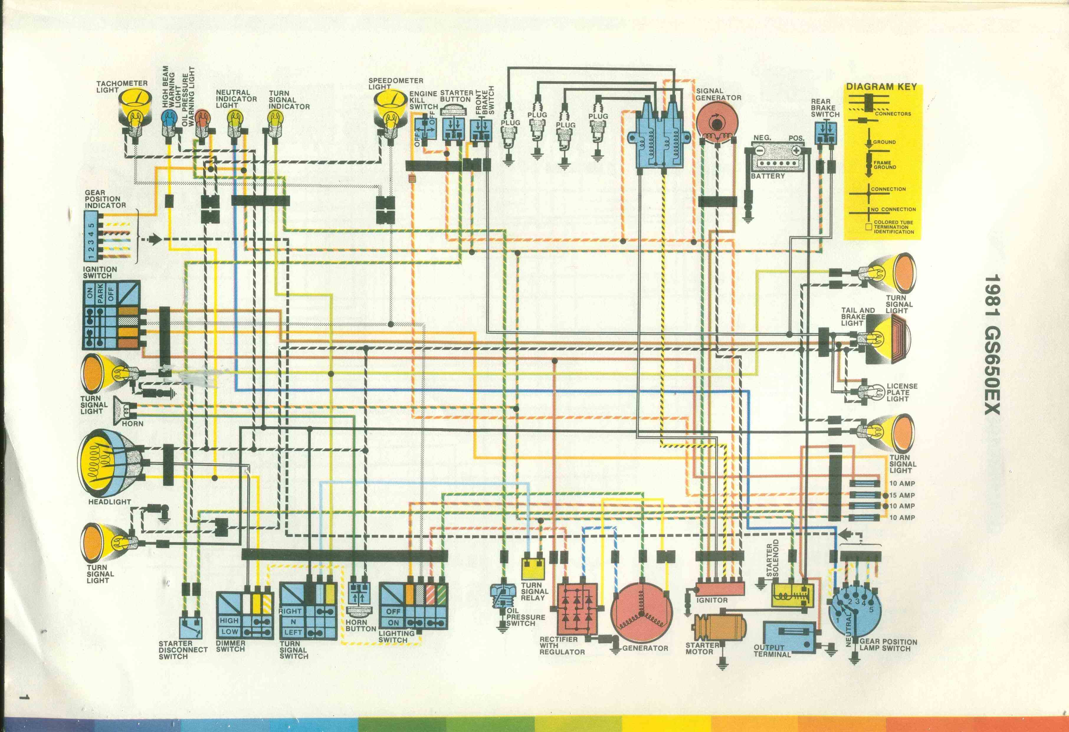
Based on the message, we need the bike to run. We also need it to have a headlamp, a tail lamp, and a horn. We need to know what we can get rid of, what we can keep. No problem! I’ll be consulting this wiring diagram as we go. Wiring diagrams are confusing, but I’ll do my best to help you out.
Electrical Tools & Supplies
You’re dead in the water without the right tools and supplies. For this project, you need a way to cut, strip, and crimp wires. You can find most of what you need on eBay.
You also need proper connectors to rig everything up.
2, 3, 4, 6, and 8-pin Connectors
And some extra wire and heat shrink, along with electrical tape.
Making the bike run
You need a working ignitor, two coils, a kill switch, a start button, working ignition pick-ups, a working stator, and a working rectifier/regulator. How the hell do you hook all of that up? Let’s talk about how the bike works.
A sensor, or pick-up, or signal generator near the crankshaft tells the ignitor when to fire the coils. So the ignitor has to be hooked up to the signal generator and the coils. If you know all of the parts came from the same bike, you might be able to look at the colors and match them up like that, or at least use the colors to be reasonably sure you’ve hooked everything up properly.
Pick up your ignitor box and look at the wires coming out of it. There should be six of them. Starting on the left, this is what each wire does, where it goes:
- Black/White: Signal generator.
- Orange/White: 12V coil power
- Black/Yellow: Coil signal
- White: The other coil signal
- Brown: Signal generator
- Green/White: Signal generator

Notice how there’s only three places any of the wires on the ignitor go: signal generator, coils, and a 12V power source. Cool eh? Unfortunately you can’t just “hook ’em all up” and ride off into the sunset. If you left the 12V power on all the time, you’d drain your battery pretty fast. So you need some kind of switch for that. Also to turn the bike off after you get it started. And to turn it off in case the throttle gets stuck open. Oh yeah, and a way to start it because bump-starting sucks.
I’m assuming you still have your stock right-side switches. There should be 3 wires coming out of them. In no particular order:
- 2x Orange/White
- Green/yellow
Ideally we’d like the start button to work ONLY IF the kill switch is set to “run.” If you’re using a keyed ignition, or a hidden ignition switch, then you’ll have to make sure the button only works when that’s on, too. Hopefully You’ll have some idea of how to add a keyed ignition after I explain how to make it work with just the kill switch and the start button. First let’s zoom in on the section of the diagram depicting the switch and the button:
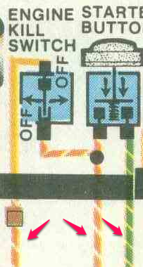 See? Three wires. I cut the image a bit short to keep other shit from intruding. Let’s talk about how they work, assuming you cut the connector off and just have three wires danging from your switches. The black rectangle is supposed to depict the stock connector.
The wire on the far left of the image goes to the positive (+) terminal on the battery. You’ll need a fuse between the battery and the switch.
The wire in the middle, same color as the first one, powers the ignitor box and your coils.
The far right wire lights up your starter solenoid and makes your starter turn when you push the button.
The kill switch and the start button are wired together inside the switch housing, so you shouldn’t have to worry about that part.
If I remember correctly, the starter solenoid has just one wire going into it. It grounds itself as soon as you bolt it to the bike. Then you just run a cable from your battery to one of the posts on the solenoid and another cable from the other post to the starter itself.
Wiring up the rest of the ignitor box should be pretty straight forward from here, especially if the wires on your signal generator and your coils match up. If not you might have to do some experimenting to figure out how the signal generator and the coils are supposed to be hooked up.
TROUBLESHOOTING TIP: If you’re pretty sure everything’s hooked up right, but the bike still doesn’t spark, try swapping the brown wire and the green/white wire on the signal generator. If the bike sparks, but it doesn’t want to run, only backfires every dozen or so cranks, then you need to swap the signal wires going to the coil. It’s easy to get those coil wires mixed up. I’m pretty sure you won’t blow your bike up if you hook them up wrong, but your mileage may vary. The bike *WILL NOT* start with the coil wires hooked up wrong.
And if I’m remembering right, I’m not even sure if there was a third wire on the signal generator. The bike might run without that first black/white wire that’s supposed to go from the signal generator to the ignitor. If it’s there, hook it up. If not, see if it sparks without it.
There are only two sets of wires you need to concern yourself with on the engine to make it run. One set belongs to your stator, and the other set belongs to your signal generator. The stator wires are yellow, and there should be three of them. The signal generator wires should be brown and green/white, but they could be just about anything given how old these bikes are, how many times parts have been changed or repaired, etc. I never trust the colors, but if they match it contributes to my belief that I’m headed in the right direction. 😛
You can check for spark without having the kill switch, start button, or start solenoid hooked up all the way. The easiest way to check for spark is to hook the ignitor up to a 12V source, the signal generator, and the coils. Make sure the coils are getting 12V. Run a cable from your battery to a post on the starter solenoid, then another cable from the other post to the starter. Make sure your battery is grounded. Now jump the posts on the starter solenoid with a screwdriver and check for spark. I do this before I bother with anything else because I don’t like doing a bunch of work just to find out I have a busted ignitor, starter, or whatever.
You can do it without the solenoid, too. Just hook the battery directly to the starter and ground the negative terminal against the frame. Bam. Starter turns. Of course you might not be able to do all of this with just two hands. Get creative or ask a friend to look for spark while you mess with the battery. You don’t need to run a bunch of wires just to find out if your parts are good.
At this point you should have a starter that only turns when the button is pressed and the switch is set to “run,” and you should have a bike that sparks and maybe even runs. Now we need to figure out how to charge the battery while the bike is running. We also need lights.
Charging system
Remember the yellow stator wires from before? Those go into a part called a rectifier regulator. The rectifier regulator turns AC voltage FROM the stator into DC voltage FOR the battery. It gets hooked up a lot like the ignitor box.
The yellow wires on the rectifier regulator go to the stator. The other wires go to the positive battery terminal, a ground, and perhaps a keyed or switched 12V source.
They’re pretty universal, too. I used one from an old Honda CB on the GS above. It worked fine. Some rectifier regulators only have 1 input wire rather than 3. Just run the 3 from the stator into the 1 on the rectifer regulator. And don’t trust the colors, whatever you do.
It always helps me to remember that there are wires going INTO the rectifier regulator from the stator/generator and OUT of the rectifier regulator to charge the battery. It takes the electricity from the generator and converts it into something the battery can use.
Lights and horn
I strongly recommend using two solenoids, also called relays, one for your high beam and one for your low beam. I used relays like these on eBay. You’ll need a third for your horn.
I wired my lights to light up whenever the kill switch was set to run.
Your headlamp relays work just like the starter solenoid does. There’s a power in from the battery, a power out to the lamp, and ground and positive wires to trigger the relay. The only thing that makes it complicated is we’ll need a second switch to activate the high beam.
Wire the first relay up so it powers the low beam when the kill switch is set to “run.” Then get another switch and use it to trigger the second relay to power the high beam.
Because the tail lamp doesn’t draw a ton of power, I wired it directly to the kill switch. Your tail lamp should have a dual filament bulb, with one filament running continuously and the other only coming on when you activate one of the brake switches. You’ll need to figure out which wire from your tail lamp needs continuous power, and which wire needs power triggered from the brake switch. The other wire goes to ground. The brake switch is a simple open/closed switch that powers the second filament on the tail lamp.